


Se fija en NMS, se publican las últimas noticas de NMS para que conozca la información tridimensional más rápida, calificada, abundante y se expresa la posición de NMS.
 Portada >
Noticias corporativas >
Designing a Crushing & Screening Plant – Part I. Primary Jaw Crushing Stage
Portada >
Noticias corporativas >
Designing a Crushing & Screening Plant – Part I. Primary Jaw Crushing Stage
 2020.10.27
Introduction
The jaw crusher is the first stage in the crushing and screening process, the main purpose of this stage is to crush the rock into a conveyable size. In addition to this, other tasks are also performed such as:
With this in mind the design of the primary jaw crusher stage is more than just getting the blasted material into the jaw crusher. The positioning of heavy-duty screening and where in the stage the screen should be position must also be addressed.
This paper aims to give some further insight into the design of jaw crusher stages and highlight some of the alternatives and best practices.
Process Layout
The simplest design of the jaw crusher stage is to feed all material directly into the jaw crusher from the dump hopper, see Figure 1.
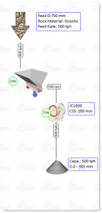
Figure 1. The simplest possible jaw crusher stage: Feeding all material from the dump hopper into the jaw crusher.
This is not an efficient design though, since the feed contains a lot of fine and mid-size material that will not be crushed and just take up space in the crusher. Feeding finer material into the crusher has no benefit and will just require an unnecessarily big crusher. This will have a direct impact on reduction since a bigger crusher cannot be operated on a small CSS (compare CSS in Figure 1 and Figure 2). In addition to this the feed containing fines will generate bigger crushing forces due to packing, this will further restrict the CSS. So the end result is obvious if the product in Figure 1 is compared with the product in Figure 2: It is almost 100 mm smaller from the process in Figure 2 and the crusher is smaller and thereby also cheaper. Running the jaw crusher on a larger CSS will also affect the secondary stage. The secondary crusher must have a larger intake and do more work. The same reasoning will then apply to the third stage where it also will be fed with a coarser feed. In the end, to reach the required plant reduction, an extra crushing stage will be needed just because the reduction in the primary stage is insufficient. As always, what you save in one stage can cause increased cost in the next.
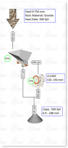
Figure 2. Jaw crusher stage where the grizzly feeder allows for material to by-pass.
Another aspect of crusher selection is to find the right sized crusher. Since CSS affects crusher capacity there could often be several suitable crushers, smaller crushers that will reach the needed capacity by running on a larger CSS, and bigger (and more expensive) crushers that could reach the same capacity at a smaller CSS. This is a tradeoff that needs to be balanced during the plant design. Often it does not make sense to spend to much time on this before the design of the secondary stage is under way. The reason for this is that the jaw crusher CSS affects the top-size of the material going to the secondary stage. This will have a big influence on the selection and tuning of the secondary crusher. More about this topic in part 2 of Design of Crushing and Screening plants: Secondary Stage.
From the basic design with a grizzly feeder and a jaw crusher (depicted in Figure 2) it is possible to further improve the crushing stage to suit the given conditions. What if there is soil, natural fines or other contaminants in the feed? This is typically material that needs to be removed as early as possible in the process. Leaving it in and removing it at a later stage will have no benefit.
If the material that should be removed separates easily from the rock it can be removed by screening the material in the bypass. From a process point of view the simplest way to achieve this is to use a grizzly feeder with a second screen deck, Figure 3.
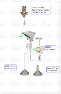
Figure 3. Jaw crusher stage where the grizzly feeder has a second deck installed to remove soil and other contaminants.
As mentioned above a second task for the primary stage could be to produce coarser products like road base and sub base. To do that a screen is needed and there are two positions where it can be installed, after the grizzly by-pass (see Figure 4) or just before the stockpile (see Figure 5).
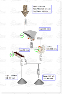
Figure 4. Jaw crusher stage with a screen in the grizzly by-pass to extract a 0-90 mm product.
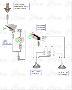
Figure 5. Jaw crusher stage with a screen that process all material and allows for production of 0-30 mm, 0-60 mm or 0‑90 mm.
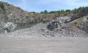
Figure 6. The rock size varies in the muck pile, as seen in the picture the number of large rocks is far greater on the right side.
As seen in Figure 5 a three deck screen has been selected and after the screen there are a number of splits that will allow the producer to select whether the 30-60 mm and the 60-90 mm fraction should be stockpiled for further crushing or extracted as a base material product. Options like this allows for greater flexibility in the plant and makes it possible to easily produce 3 different base material products.
Another factor that will impact the positioning of the screen in the process is blasting damage to the material. In some cases there are significant amounts of cracks in the rocks which gives weaker material. If this is the case the screen should be positioned as in Figure 5. This will remove damage material to a great extent and leave the un-damage material in the process. On the other side, if this is not the case this solution can come at a cost since material that could be further processed to high value product is extracted as low value product. This is also a good position to have the screen if clay or other sticky material should be removed by washing.
Equipment Sizing
Sizing of equipment for the primary stage requires some extra thoughts. This is mainly due to two dynamic factors: The delivery of material with vehicles and the changes in gradation caused by where in the muck pile the material is extracted, see Figure 6. In other words, it cannot be assumed that the operating conditions are not varying over time.
The dynamic operating conditions will therefore demand that extra capacity is designed into the process. The crushing stage must be able to handle a situation where the delivery of material gets delayed for a short period of time and then more material than normal will arrive. The first measure to address this is to have a dump hopper of sufficient size. To handle trucks coming at shorter than normal interval and to minimize the risk of running empty the recommendation is to make the hopper big enough to fit 1.5 to 2 times the haul truck bed capacity.
The second scenario that must be addressed is that the material that is fed to the plant is coarser than normal. (Finer feed seldom causes major problems in the primary stage). If the crushing stage in Figure 7 is used as an example. As it is shown 58% (288 tph/500tph) of the feed is larger than the grizzly separation and will be crushed in the jaw crusher. Let us say that this changes due to feed from a section in the muck pile where the material is much coarser. Instead of 58% passing over the grizzly the amount will increase to 70% (350 tph). If the jaw crusher would have been sized at 100% capacity utilization (instead of 76%) it would not have been able to handle this and the plant would immediately start losing production.
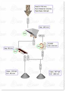
Figure 7. The jaw crusher stage with the normally expected operating conditions.
A good rule of thumb for equipment capacity in a primary crusher stage is therefore to aim at 70-75% capacity utilization. This will normally give enough margin to handle the given uncertainties in operating conditions. Another good rule of thumb for the design of jaw crusher stages is to start with the same setting on the grizzly separation and the jaw crusher CSS. This will often create good operating conditions with a reasonable balance between crusher capacity and by-pass. The size distribution in the stockpile will then be well suited for further processing.
As seen in Figure 7 the 70-75% target is not really fulfilled, the crusher is 1% above. The question is then how should this be solved? We do not want to select a larger crusher to address the fact that we are 1% over target since this will be a massive increase in investment cost. For the process there are two options, change the grizzly separation or increase the jaw crusher CSS. The grizzly separation can be seen as the easiest option, but one must be aware that for many grizzly feeders the separation size cannot be freely selected due to the design with fixed sized bars. To show the principal it is assumed that in this case it is possible to change the separation from 160 mm to 175 mm. The result is shown in Figure 8 below. We can see that the crusher capacity utilization decreased to 73% without any other notable effect.
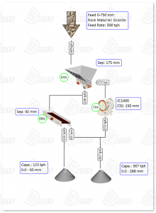
Figure 8. The grizzly separation has been increased to 175 mm which has decreased the jaw crusher capacity utilization from 76% to 73%
The other option to increase the jaw crusher CSS is shown in Figure 9. The CSS has been increased from 150 mm to 160 mm and that has dropped the capacity utilization to 72%. The downside with increasing the CSS is that the product size increases. When comparing the stockpile top size in Figure 8 and Figure 9 the size have increased from 288 mm to 310 mm. This could in turn have a downstream effect on the secondary crusher where a coarser chamber must be selected which in turn will limit the reduction capability of that crusher.
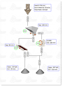
Figure 9. The jaw crusher CSS has been increased to 160 mm which has decreased the jaw crusher capacity utilization from 76% to 72%
If the design method described above is considered the stage will often be both cost efficient and robust. It will produce a feed for the secondary stage that has the potential for efficiently producing aggregates of the desired amount and quality.
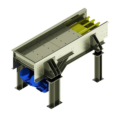
One final tip for a well-designed jaw crusher stage is to consider having a vibrating feeder under the jaw crusher. The purpose of this feeder is to protect the underlying belt from impacts when rocks falls out of the jaw crusher. This is especially useful on bigger crushers where the rocks coming from the crusher can be large and reach high speed before hitting the underlying belt conveyor. This impact can cause damage to the belt which will need frequent replacement. The vibrating feeder is much better suited to take the impact and the wear plate is cheaper to replace than the conveyor belt.
Conclusions
As this paper has shown the design of jaw crusher stages are fairly simple from a process point of view. Instead it is knowledge about the local conditions and properties of the feed material that make the design process challenging. This includes handling of unwanted material and/or production of course products. It is important to think this through in order to be efficient and produce material with the right properties for further processing. Screening out unwanted material at the best spot will have a significant impact on the process productivity. The design of the stage should also be done to allow the secondary stage to operate efficiently. It is therefore beneficial to make a preliminary design of the primary stage and then do the final tuning together with the secondary stage.


 Idiomas
 中文
中文 English
 Español
 South Africa
 Previa:NMS Held the 2nd Large-scale Theme Academic Salon …
